
O. Zadakbar∗, A. Vatani and K. Karimpour
.Faculty of Chemical Engineering, University College of Engineering, University of Tehran, No. 8 Khoshnevis St
Isargaran St. Valfajr St. Kashani Ave., Postal Code: 1474674784, Tehran-Iran
e-mail: zadakbar@aim.com – avatani@ut.ac.ir – kianoosh_karimpour@yahoo.com
Corresponding author*
Abstract — Flare Gas Recovery in Oil and Gas Refineries —Environmental and economic considerations have increased the use of gas recovery systems. Regarding our comprehensive process evaluation in 11 oil and gas refineries, we devised practical methods to approach zero flaring. This paper presents the results of two case studies of reducing, recovering and reusing flare gases from the Tabriz Petroleum Refinery and Shahid Hashemi-Nejad (Khangiran) Natural Gas Refinery, both in Iran. The design considerations, economics of the process and system operation are studied in this paper. Flare gases are compressed and returned to the fuel gas header for immediate use as fuel gas. Flare gas recovery reduces noise and thermal radiation, operating and maintenance costs, air pollution and emission, and fuel gas and steam consumption. Process stability and flare tip increment without any impact on the existing safety relief system are also the effects of the flare gas recovery system.
INTRODUCTION
Worldwide, final product costs of refinery operations are becoming proportionally more dependent on processing fuel costs, particularly in the current market, where reduced demand results in disruption of the optimum energy network through slack capacity [1]. Therefore, to achieve the most cost-beneficial plant, the recovery of hydrocarbon gases discharged to the flare relief system is vital. Heaters and steam generation fuel provision by flare gas recovery leaves more in fuel processing and thus yield increment. Advantages are also obtained from reduced flaring pollution and extended tip life [1].
During recent years in Iran, all projects have included the collection of associated gases. Thus, flare gas recovery in oil and gas refineries are going to be neglected.
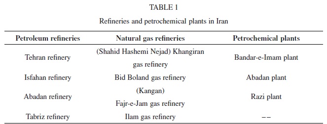
Therefore, in the present work, investigations were made into the operational conditions of 11 important refineries and petrochemical plants. After comprehensive evaluations, we devised practical methods to reduce, recover and reuse flare gases for each petroleum refinery, natural gas refinery and petrochemical plant. The list of refineries and petrochemical plants is shown in Table 1.
1. COMPREHENSIVE PROCESS INVESTIGATION
Adequate process evaluation of plants, especially the units that produce flare gases, comprehensive monitoring of flow and composition of flare gases, investigation of existing flare systems, and finding alternative choices for reusing flare gases were carried out in 11 petroleum refineries, natural gas refineries and petrochemical plants. The results of the investigation of the existing flare systems, finding alternative choices for reusing flare gases and the overall flare gas recovery system are discussed below.
1.1 Investigation into the Existing Flare Systems
Flare tips are exposed to direct flame during their service life, which can of course be quite damaging. As a result, flare tips need to periodically be taken out of service and refurbished, which adds to production costs. The life of a flare tip is related to the amount of usage. Some of the flares were revealed to burn excess gas due to tip damage. By repairing or replacing these tips, purge gas will be reduced. Natural gases are typically used as purge gases. This use of natural gases for twenty-four hours each day is not only wasteful of a precious natural resource, it is also very expensive and can represent an expenditure of many tens of thousands of dollars per year. Since air is caused to enter the flare system from the atmosphere only when there is a decrease in the temperature of the gas contained in the pressure-tight flare system, there is a need for purge or sweep gases only when there is a decrease in the temperature of the internal gas content of the flare system.
For this reason, there is no need for around-the-clock injection of purge gas for the purpose of avoiding entry of air into the flare system. However, to date, there has been no system for automated injection of purge gases into flare systems only as they are needed, due to gas system temperature decrease. Providing a pair of temperature sensors in the flare gas line is an alternative way to decrease purge gases. These two sensors are placed in close proximity. One is a fast-acting sensor, which responds rapidly to any change in temperature. The other is a slow-acting sensor, which responds lowly to a change in temperature.
Thus, in combination, they provide a sensor system sensitive to change in temperature in the flare gas line [2]. To save gas burning, it is recommended to repair or replace pilots with more reliable ones. Also, in some refineries, many ignition systems are fitted, but never in use, because they simply do not work when they are needed. As a result, purge gas is increased to enhance the reliability of the flare. Multi-pilot gas conservation systems are recommended for ignition of waste gas from a flare burner, provisions being made to reduce or limit the pilots for ignition at the most effective location as determined by the wind direction and further, if desired by the wind velocity, a reduction in the number of pilots, effecting substantial savings of combustible gas [3]. A pilotless flare ignitor is an alternative choice too. A pilotless flare ignitor is capable of igniting waste gas issuing continually or sporadically from a flare stack and includes an ignitor housing with an open end which extends into the flare stack.
In some areas a large number of flare stacks have been installed. Global studies recommended optimizing the existing number of flares [4].
In some areas the maximum design capacity of the equipment was reached. Hence, surplus gas is being flared. The studies identified equipment that can be debottlenecked; otherwise, additional new units need to be installed [4].
1.2 Finding Local Alternative Choices for Reducing and Reusing Flare Gases
Some storage tanks are fixed roof types that require positive pressure set at a certain point. The tank is directly connected to a flare. One of the studies recommended a flow suction tank gas recovery system to be installed at each fixed roof storage tank. The vapor jet system is an alternative to conventional vapor recovery technology for the recovery of hydrocarbon vapors from oil production facilities’ storage tanks. The process utilizes a pump to pressurize a stream of produced water to serve as the operating medium for a jet pump [1].
In particular, the refinery off gases from a FCCU contain olefin components, up to about 20 percent by volume ethylene and up to about 11 percent by volume propylene, which components normally are not recovered from the off gases, but which components may have value to warrant recovery and use in other petrochemical processes or uses in downstream processing [1].
Delayed coking operations increase the volume of byproduct non-condensable hydrocarbons generated and typically flared. A local flare gas recovery system on a delayed cocker unit is capable of recovering a huge amount of flare gases from the delayed cocker [5].
Using some new environmentally friendly technologies reduces flare emissions and the loss of salable liquid petroleum products to the fuel gas system. New waste heat refrigeration units are useful for using low temperature waste heat to achieve sub-zero refrigeration temperatures with the capability of dual temperature loads in a refinery setting. These systems are applied to the refinery’s fuel gas makeup streams to condense salable liquid hydrocarbon products [6].
1.3 Flare Gas Recovery System
Environmental and economic considerations have increased the use of gas recovery systems to reclaim gases from vent header systems for other uses. Typically, the gas is recovered from a vent header feeding a flare. Depending on vent gas composition, the recovered gas may be recycled back into the process for its material value or used as fuel gas. Vent gas recovery systems are commonly used in refineries to recover flammable gas for reuse as fuel for process heaters [1]. The Tabriz petroleum refinery and Shahid Hashemi-Nejad (Khangiran) gas refinery are the most important parts of our work. The results of these case studies are discussed.
1.3.1 Flare Gas Recovery for the Tabriz Petroleum Refinery
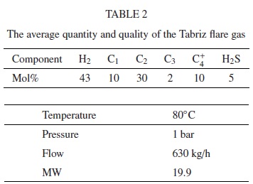
The Tabriz petroleum refinery consists of 14 refining units and 10 units related to other services. The nominal capacity of the Tabriz refinery is 80000 barrels per day, but by executing the authorities’ augmenting schemes, nominal capacity has been increased to 115000 barrels per day. The crude oil, up to 115000 barrels in a day, is brought from crude oil preserving tanks to a distillation unit in order to be separated into oil cuts. The necessary crude oil is supplied from the Ahwaz oil fields via a 16-inch pipeline. The Tabriz petroleum refinery normally burns off 630 kg/h gas in flare stacks [7]. The average quantity and quality of flare gas are shown in Table 2.
Having investigated the operational conditions of the Tabriz petroleum refinery, especially the units which produced flare gases, we proposed practical methods to reduce, recover and reuse flare gases for the Tabriz petroleum refinery.
There are some alternative choices for using recovered gases. The most important choices are: using flare gases as fuel gas, for electricity generation and as feed gas. In the next step, we tried to find the best choice for using recovered flare gases. Regarding the operational and economic evaluation, recovery of hydrocarbon gases discharged to the flare relief system is probably the most cost-beneficial plant retrofit available to the refinery. Use of flare gases to provide fuel for process heaters and steam generation leaves more in fuel processing, thus increasing yields. Regarding the results of data analyses, the mean value of molecular weight of the gas is 19.9, and the flow discharge rate is modulated between 0 and a maximum of 800 kg/h. The average temperature is 80◦C and the average pressure is 1 bar.
1.3.2 Flare Gas Recovery for the Shahid Hashemi-Nejad (Khangiran) Gas Refinery
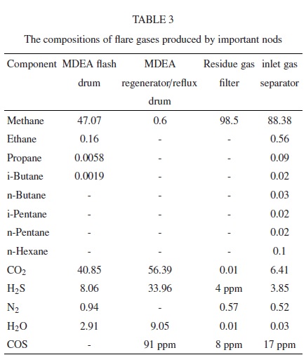
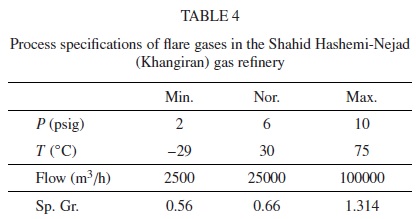
The Shahid Hashemi-Nejad (Khangiran) is one of the most important gas refineries in Iran. The necessary natural gas is supplied from the Mozdouran gas fields. The Shahid Hashemi-Nejad (Khangiran) Gas Company consists of 5 sour gas refineries, 3 dehydration units, 3 sulfur recovery units, 2 distillation units, 2 stabilizer units and 14 additional units related to other services. The Shahid Hashemi-Nejad (Khangiran) gas refinery normally burns off 25000 m3/h gas in flare stacks [8]. The analysis of operational conditions shows that some units normally produce flare gases more than other units. The compositions of flare gases produced by these units are shown in Table 3. These streams make the main flare stream. In addition, the process specifications of flare gases in the Shahid Hashemi-Nejad (Khangiran) gas refinery are shown in Table 4.
After a comprehensive process evaluation, we devised practical methods to reduce, recover and reuse flare gases for the Shahid Hashemi-Nejad (Khangiran) gas refinery. In addition, the flame igniter system, the flame safeguards and the existing flare tip have to be replaced.
The fuel gas of the Shahid Hashemi-Nejad (Khangiran) gas refinery is supplied by sweet gas treated in the gas treating unit (GTU). Due to a pressure drop in the gas distribution network in Mashhad city in the northeast of Iran, during cold seasons, they encourage using flare gases as an alternative fuel gas resource and eliminating the use of sweet gas produced in a GTU. Regarding the Shahid Hashemi-Nejad (Khangiran) gas refinery recommendations and the operational evaluations, recovery of hydrocarbon gases discharged to the flare relief system is probably the most cost-beneficial plant retrofit available to the refinery.
2. FGRS DESIGN
2.1 Flare Gas Design for the Tabriz Petroleum Refinery
The design considerations include: the flare relief operation and liquid seal drum, the flow and composition of flare gases and the refinery fuel system. The considerations led to a unit design for normal capacity up to 630 kg/h. Our proposed flare gas recovery system is a skid-mounted package which is located downstream of the knockout drum, as all flare gases from various units in the refinery are available at this single point. It is located upstream of the liquid seal drum as pressure control at the suction to the compressor will be maintained precisely, by keeping the height of the water column in the drum. The compressor selection and design depends on the system capacity and turndown capability [9]. The most appropriate type and number of
compressors for the application are selected during the design phase of the project. Liquid ring compressor technology is commonly used because of its rugged construction and resistance to liquid slugs and dirty gas fouling [1]. A number of characteristics which must be taken into account when compressing flare gas are as follows:
The amount of gas is not constant, the composition of the gas varies over a wide range, the gas contains components which condense during compression, and the gas contains corrosive components [10].
A modular design which includes two separate and parallel trains capable of handling various gas loads and compositions is recommended for the Tabriz petroleum refinery.
The recommended system consists of compressors which take suction from the flare gas header upstream of the liquid seal drum, compress the gas and cool it for reuse in the refinery fuel gas system. It includes two LR compressors, two horizontal 3-phase separators, two water coolers, piping and instruments. The compressed gas is routed to the amine treatment system for H2S removal. The effect of the devised FGRS on flaring in Tabriz petroleum refinery is shown in Figure 1.
The FGR system with LR compressor for the Tabriz petroleum refinery is shown in Figure 2.
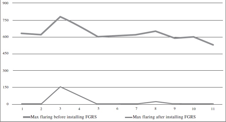
Max. monthly gas flaring before (up) and after (down) installing the FGRS in Tabriz petroleum refinery (kg/h)
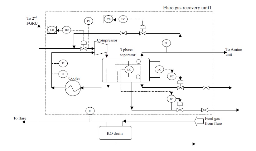
The first unit of the FGR system for the Tabriz petroleum refinery
2.2 Flare Gas Design for the Shahid Hashemi-Nejad (Khangiran) Gas Refinery
In this case, the considerations led to a unit design for normal capacity up to 25000 m3/h. The process specifications
of the outlet must be similar to refinery fuel gas. The proposed flare gas recovery system is like the proposed system for the Tabriz petroleum refinery. It has a modular design and comprises three separate and parallel trains capable of handling various gas loads and compositions.
3. SAFETY AND CONTROL
The principal potential safety risk involved in integrating a flare gas recovery system is from ingression of air into the flare header, which can be induced by the compressor suction. This could result in a flammable gas mixture being flashed off inside the system from flare pilots [4]. It should be noted that the FGR unit does not interrupt the flare system and should be able to handle sudden increases in load. Therefore, no modification to the existing flare system will be attempted, but with two exceptions. The connections through which the compressors will take suction on the system, and additional seal drums which will provide extra safety against air leakage into the flare system and allow the buildup of flare header pressure, during compressor shutdown or flare gas overload. Also, the compressor control system does not affect the flare system pressure and thus its design will be able to avoid low pressure suction in the flare system during normal operation. When the compressors are not functioning properly, automatic or manual shutdown should result. The flare system will operate as it does now with no compressors. Meanwhile, if the volume of flare gases relieved into the flare system exceeds the capacity of the FGR unit, the excess gases will flow to the flare stack.
If this volume is less than the full capacity of the FGR unit, a spillback valve will divert the discharged gases back to the suction zone to keep the capacity of the flare gas recovery unit constant.
Other safeguards to the flare system against air leakage are [4]:
– the fail-safe shutdown of the FGR unit compressors on low pressure in the flare system.
– the shutdown of the FGR unit compressors upon high inlet and/or outlet temperatures.
– adequate purge connections in the downstream of the seal drum.
– low flow switches in the purge line to the main flare header downstream of the seal drum, to cut in fuel gas as purge gas.
4. ECONOMICS AND EMISSION CONTROL
In this section, the results of economic evaluations and the results of emission control are presented. These results were obtained based on 0.11 $/m3 for fuel gas, 6 $/ton for steam and 5 cent/kWh for electricity.
4.1 Economic Evaluations for the Tabriz Petroleum Refinery
The recommended system includes two LR compressors, two horizontal 3-phase separators, two water coolers, piping and instruments. Capital investment to install the FGR system is $0.7 million which, including maintenance, amortization and taxes, corresponds to a payback period of approximately 20 months. Another essential effect of using the FGRS is gas emission reduction. By using the FGRS in the Tabriz petroleum refinery, we can decrease up to 85% of the gas emission including CO2, CO, NOx, SOx, etc.

4.2 Economic Evaluations for the Shahid Hashemi-Nejad (Khangiran) Gas Refinery
The proposed system for the Shahid Hashemi-Nejad (Khangiran) gas refinery has three LR compressors, three horizontal 3-phase separators, three water coolers, piping and instruments. Capital investment to install the FGR system is $1.4 million, which includes maintenance, amortization and taxes, with a payback period of approximately 4 months. We can decrease up to 70% of the gas emission by using the FGRS in the Shahid Hashemi-Nejad (Khangiran) gas refinery.
CONCLUSION
It is well known that there are many economical ways to achieve flaring minimization and gas conservation in oil and gas refineries. In order to find these ways, a comprehensive process evaluation of plants, especially units that produce flare gases, comprehensive monitoring of flow and composition of flare gases, investigation of existing flare systems and finding alternative choices for reusing flare gases was carried out in 11 petroleum refineries, natural gas refineries and petrochemical plants. Based on our comprehensive process evaluation, we devised alternatives to reduce gas flaring.
Recovery of hydrocarbon gases discharged to the flare relief system is probably the most cost-beneficial plant retrofit available to the Shahid Hashemi-Nejad (Khangiran) gas refinery and the Tabriz petroleum refinery. Use of flare gas to provide fuel for process heaters and steam generation leaves more in fuel processing, thus increasing yields. Advantages are also obtained from reduced flaring pollution and extended tip life. In the Tabriz petroleum refinery, 630 kg/h flare gas will be used as fuel gas by $0.7 million capital investment corresponds to a payback period of approximately 20 months, and also 85% of gas emissions will be decreased. In the Shahid Hashemi-Nejad (Khangiran) gas recovery, 25000 m3/h flare gas will be used as fuel gas by $1.4 million capital investment corresponds to a payback period of approximately 4 months, and 70% of gas emissions will be decreased.
REFERENCES
1 Zadakbar O., Karimpour K., Zadakbar A. (2006) Flare Gas Reduction and Recovery, The First National Specialty Conference on Gas, Iran, Oct. 30-31.
2 Reed, Robert D. (1981) Control System for Purge Gas to Flare, United States Patent 4265611.
3 Straitz, III, John F. (1978) Flare Gas Stack with Purge Gas Conservation System, United States Patent 4101261.
4 Tarmoom I.O. (1999), Gas Conservation and Flaring Minimization, Paper SPE 53321, SPE Middle East Oil Show, Bahrain, Feb. 20-23.
5 Sharama R.K. (2007) Minimize Your Refinery Flaring, Hydrocarb. Process. 86, 2, 105-106.
6 Brant B., Brueske S. (1998) New Waste-Heat Refrigeration Unit Cuts Flaring Reduces Pollution, Oil Gas J. 96, 20, 61-65.
7 http://www.tbzrefinery.co.ir
8 http://www.khangiran.ir
9 Fisher P. (2002) Minimize Flaring by Flare Gas Recovery, Hydrocarb. Process. 81, 6, 83-85.
10 Alcazar C., Amilio M. (1984) Get Fuel Gas from Flare, Hydrocarb. Process. 64, 7, 63-64.


