
Matthias Bauer, TECON Engineering; Mario Köck, TPS;
Klaus Jörg and Chandrasekhar Ramakrishnan, TECON Engineering; and Andreas Scheed, OMV
Summary
The full-length paper describes the project evolution, from the first study to the implementable concept of energy production using the associated gas of two onshore facilities in Tunisia. Despite its complex composition, high carbon dioxide (CO2) content, high hydrogen sulfide (H2S) concentration, and the relatively low quantities of available flared gas, a technically and economically feasible solution was developed successfully.
Introduction
Thyna Petroleum Services (TPS) is a Tunisian joint-venture corporation of the Tunisian governmental oil and gas company, Entreprise Tunisienne d’Activités Pétrolières (ETAP), and the Austrian oil and gas affiliated group OMV AG based in Sfax. One of the future objectives of TPS is to avoid, or at least reduce, flaring of associated
gas contained in crude oil during oil production. A particular challenge is to discover a process that enables the use of the associated gas despite its untypical gas composition for valorization processes.
Use of the associated gas will also reduce greenhouse-gas emissions. Therefore, this project also could be considered as a Clean Development Mechanism (CDM) project (United Nations 2010).
CDM is an arrangement under the Kyoto Protocol that allows industrialized countries with an emission-reduction or emission-limitation commitment to invest in an emission-reduction project in developing countries as an alternative to more-expensive emission reductions in their own countries. Such projects can earn saleable certified-emission-reduction (CER) credits, each equivalent to 1 ton of CO2, which can be counted toward meeting the Kyoto targets.
Increasing energy prices over the last few years, as well as enhancements in the process area, make the use of associated gas more and more interesting. Furthermore, the pressure of environmental and political organizations to develop new alternatives to flaring is constantly rising.
Current Gas Flaring at TPS Stations
TPS currently operates three crude-oil-preconditioning plants. There are two onshore facilities, “Tank Battery” and “Guebiba Station” near Sfax, and one offshore facility, “Cercina Delta Platform,” close to Kerkennah Island, located approximately 30 km from Sfax. Associated gas, which accrues from the conditioning process, is currently flared at all three process facilities, without heat recovery.
Gaining Additional Energy From Unused Resources
The increasing contamination caused by polluting emissions, together with the associated consequences on human beings, animals, and nature, results in an obligation to seek new processes for the use of potential energy sources. It is an essential challenge to find an economically and technically feasible option that would commute the existing energy value within the associated gas (heating value) into usable energy.
Possibilities of Power Generation With Gas
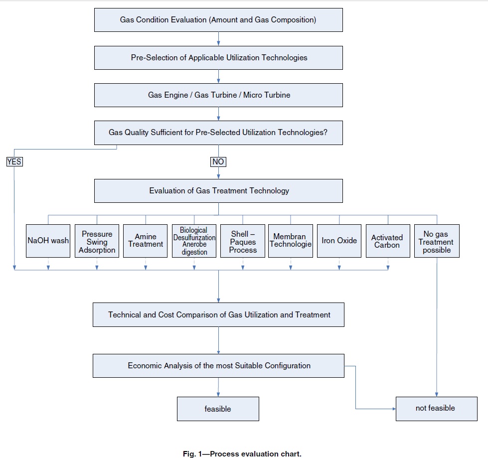
In 2008, efforts to find a possibility to use the associated gas have increased. The Austrian engineering service provider TECON was commissioned to perform a feasibility study. In the “gas valorization” feasibility study of the two onshore facilities, the possible available power-generation processes were investigated. To simplify the selection process, a process evaluation flow sheet was developed, which can be seen in Fig. 1. The first step was to conduct a preselection of possible gas-use technologies on the basis of the amount of associated gas.
Preselection of Applicable Gas Use Technologies
Because of the relatively low amount of associated gas from both stations (Tank Battery, 1,200 Nm³/h; Guebiba, 600 Nm3/h), large conventional power plants fired with the associated gas did not come into consideration. Therefore, the research focused on the following technologies for a decentralized application: gas turbine, microturbine, and gas engine. All three technologies are well suited for in-situ power generation out of the existing energy source within the associated gas field and are robust enough to resist load variations.
Turbines and microturbines are based on the same principle. As the name itself indicates, a microturbine is a turbine with a lower performance level. Although there is no clear border between turbines and microturbines, a microturbine would typically correspond to performance levels lower than 500 kW.
Gas engines are available in a broad spectrum of power ranges, typically between 20 and 1,500 kW.
Direct Use of Crude-Oil Associated Gas
Preliminary investigations focused on power generation without any pretreatment of the gas. It quickly turned out that commercial gas engines cannot operate with the extremely high H2S content of the associated gas. Further investigations identified 500 ppm H2S as a maximum limit, which allows the use of the associated gas in a gas engine.
For untreated usage within turbines, the investigations were slightly more promising. Normally, turbines can handle H2S contents up to 500 to 2,000 ppm. After intensive research, just one manufacturer was found that offers a turbine that can handle associated gas with 5,500 ppm H2S, as at Tank Battery. However, the greatest disadvantage is that the use of a turbine at Guebiba Station is not feasible. Considering that the owner (TPS) prefers identical technologies on both sites, the implementation of a turbine was no longer an option without pretreatment.
The results of the investigations into possible use of microturbines without pretreatment were unsatisfactory. Without a predesulfurization process, only one kind of microturbine with a 65-kW power output could use the associated gas from the Guebiba Station (13,400 ppm H2S), as well as that of Tank Battery. But in order to deal with the whole flow rate there, approximately 10 of these units would need to be installed in Guebiba Station, and approximately 20 units in Tank Battery. Hence, this is not recommended because of the additional requirements of space, the extended pipework needed, the subsequent maintenance on the numerous and complex instrumentation and the resulting high investment costs. After pre-treatment, microturbines with a higher power spectrum would also be an alternative.
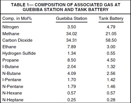
Because of the composition of the associated gas (Table 1), with respect to a very high H2S and CO2 content and relatively low CH4 content, preconditioning upstream of the energy-production plant is required. Because of the higher H2S content at the Guebiba Station, all subsequent research concentrated on this station because a feasible solution at Guebiba would also be applicable at Tank Battery.
After identification of the technical necessity of pretreatment, the next step was the selection of the best-fitting gas-conditioning process.
Requirements of Gas Conditioning
The challenge was therefore to identify a low-cost conditioning process, preferably implementable on both onshore stations. The main purpose of the conditioning treatment was to increase the lower heating value (LHV) by means of a reduction in the CO2 content, as well as a reduction in the H2S content at the same time.
With regard to the fuel requirements of most gas turbines and engines, no extra-fine desulfurization is necessary. Therefore, investigations concentrated on a maximum H2S concentration in the treated fuel gas of 500 ppm. Another requirement for the optimal gas-conditioning process is a reduction in higher hydrocarbons (C3+). This would lead to an increase in the methane number, which is also an important factor for gas engines.
Gas-Treatment Selection
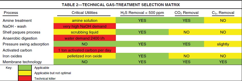
Table 2 shows the technical decision matrix for the investigated gas-conditioning technologies. With regard to the previously described criteria, eight gas-treatment technologies were compared to identify a technical and economical optimized process.
The technical comparison shows that NaOH wash, anaerobic digestion, and activated carbon will need undeliverable amounts of necessary chemical ingredients. Therefore, they were eliminated from further consideration.
The Shell Paques process and iron oxide process technologies would be theoretically applicable, but not efficient enough for a subsequent energy-production plant. Both processes do not remove or reduce the CO2 and the C3+ content. The treated gas would be less corrosive because of the reduced H2S content, but the LHV would still be in a
very low range, so they were also no longer under consideration. Consequently, the membrane process and pressure-swing-adsorption (PSA) process turned out to be technically favorable technologies.
The final decision between these two technologies was dependent on the economics. Therefore, tenders for both were requested.
The evaluation of the tenders identified that the membrane technology presented both lower capital expenditures (CAPEX) and lower operational expenditures (OPEX) than the PSA technology.
Membrane processes are often used for pretreatment downstream of fine cleaning units. The chosen membrane process is able to reduce the H2S content to approximately 300 ppm, which is a value that can be handled by gas engines as well as by microturbines, so that further fine conditioning would not be required in the present case. This fact elevates membrane technology into a position as favorite.
After technical and economical evaluation, membrane technology was chosen as the most feasible technology to treat the associated gas and bring it into a usable condition.
Gas Conditioning by Means of Membrane Technology
In general, a membrane operates on the principle of selective permeation. Each gas component has a specific permeation rate. The components with higher permeation rates (such as CO2, H2, and H2S) will permeate faster through the membrane module than components with lower permeation rates (such as N2, C1, C2, and
heavier hydrocarbons).
Fig. 2 shows a block schema of a suitable membrane unit, where a compressed gas flow is divided into two different streams plus a recirculation flow by polar solubility selective membranes. This membrane system separates C3+ hydrocarbons as well as H2S and CO2 from the associated-gas stream.
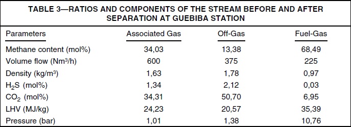
Table 3 shows the increasing associated gas quality by comparing the main input parameters and the resulting output streams after the membrane unit.
A large fraction of the gas (referred to “off-gas” in Table 3) that contains the most corrosive components and fractions of the incombustible components is separated from the main stream and directed to the flare. Despite the incombustible fractions in this offgas stream, analysis has shown that this gas is combustible in a flare by adding a specific amount of air. Flaring is the safest and cheapest way of disposing of the highly toxic H2S. Resulting SO2 emissions would also be produced in the case of direct flaring of the entire associated gas, which means that this does not constitute an additional environmental concern.
For power generation, the fuel gas is of great interest (referred as “fuel-gas” in Table 3). In fact, this resulting fuel-gas stream is approximately one-third of the of the total flow rate. However, owing to the increase in the LHV, the overall energy content does not decrease proportionally to the volume. The relevant fractions with a
high energetic value, especially CH4, remain within the gas stream.
After being isolated from all contaminating components, this outlet gas stream, in contrast to the inlet gas stream, is usable with all investigated types of power-generation facilities.
Technical and Environmental Gas-Use Technology Comparison
Following the decision on the most applicable gas-conditioning process, the most beneficial gas-use process has to be identified. As initially mentioned, the technology selection was limited to the gas engine and microturbines because of the low amount of available associated gas. In principle, all preselected technologies
are operable with the cleaned gas from the membrane.
In environmental terms, by considering CO2 emissions, all technologies return the same values. Noise disturbances can be avoided by a containerized design in all cases, and regarding dispersion and radiation, no elementary differences were calculated.
While gas engines are usually in a spectrum of approximately 40% electrical efficiency, turbines offer between 30 and 35% electrical efficiency. For this reason, a higher electrical output can be assumed by the application of gas engines.
An essential technical aspect that also influences the economics is the necessary equipment required for the correct operation of the plant. Turbines and microturbines work with higher inlet pressures than gas engines. Both at Guebiba Station and at Tank Battery, the natural-gas pressure is very low and not sufficient to operate turbine technologies, which require an inlet pressure of approximately 10 bar. Therefore, a compressor to boost the gas is required. This fact would provide the gas engine with a very crucial advantage. But because
the membrane gas conditioning also requires an inlet pressure of 10 bar, a compressor is necessary in all cases. Regarding instrumentation and control systems, all technologies are at a similar technical level.
A further advantage to gas engines is that the staff of TPS already has experience with their operation. TPS uses gas engines at some offshore wells to operate the electrical submersible pumps to pump the crude oil to the treatment platform. In contrast, TPS does not currently operate turbines or microturbines.
Summing up all previous technical and environmental aspects, the application of gas-engine technology is preferable from a technical point of view.
Nevertheless, the gap between the technologies from the technical point of view is in a range that for a final decision, a detailed economical comparison is required.
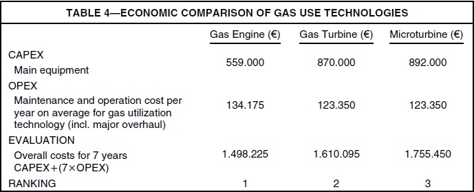
Cost Comparison of Gas-Use Technologies
Quotes were requested for all required processes. To ensure a transparent comparability, the vendors were requested to breakdown their quotes into main-equipment cost (CAPEX) and yearly operational and maintenance costs (OPEX).
The economic evaluation was executed by a comparison of CAPEX plus seven times OPEX. Because the costs for transport (which are mainly influenced by the costs for the booster, instrumentation, and control system and connection to the local electricity supply) are in a similar range, these costs were not considered in this cost comparison.
An evaluation of the values (Table 4) pointed to the gas engines being favorable from an economic point of view. Together with the fact that gas engines offer a higher electrical-output efficiency, it was concluded that gas engines present the most beneficial technical gas-use solution.
Resulting Gas to Power Configuration
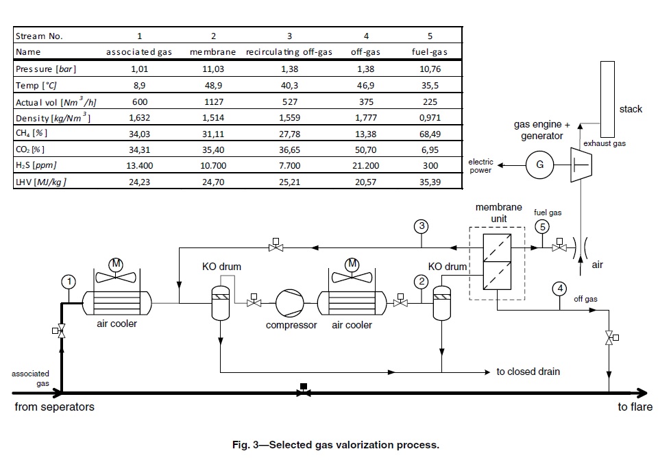
Fig. 3 shows the most beneficial technical solution developed to valorize the associated gas at the Guebiba Station and at Tank Battery. Because of the low associated-gas pressure, a prerequisite is to compress the almost atmospheric associated gas to the necessary operating pressure of the membrane unit. To avoid condensation problems in the compressors, it is necessary to cool the associated gas by an air cooler and to separate droplets out of the gas stream within a knockout drum. After the compressor, another air cooler is required to cool down the compressed gas again. The eventually condensing hydrocarbons get separated by another knockout drum before the gas stream enters the two-stage membrane unit, where the gas is divided into three resulting streams. The off-gas stream (No. 4) of the first stage gets directed to an existing flare unit. The off-gas of the second stage, which has a lower H2S and CO2 content than the off-gas of the first stage, gets recirculated. Because of the low pressure of this recirculating stream (No. 3), it is necessary to tie in upstream of the compressor. The resulting fuel gas (No. 5) with a high LHV and lower H2S and CO2 content gets mixed with air and is combusted in a gas engine. The planned configuration also has forseen the possibility to send the associated gas, as it was before the implementation of the valorization unit, directly to the flare in the case of maintenance or other reasons.
Recovered Electrical Energy
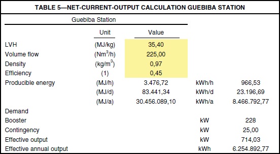
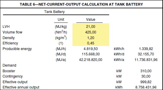
The amount of energy produced is calculated on the basis of the established gas volume flow multiplied by the fuel-gas density, its LHV, and a maximum efficiency of 45%. The energy demand of the power-generation facility itself (mostly required by the compressor)
shall be subtracted from the total output. In consideration of the points previously raised, a net current output of 0.71 MW at Guebiba Station and almost 1 MW at Tank Battery could be realized. A calculation of the net current output from both stations is shown in Tables 5 and 6.
Economic Analysis of Guebiba Station
For Guebiba Station, an economic analysis over 12 years was conducted. The investment and operational costs, including maintenance costs, were compared to the annual benefit of the produced electricity. Electricity prices were verified by the local electricity supplier.
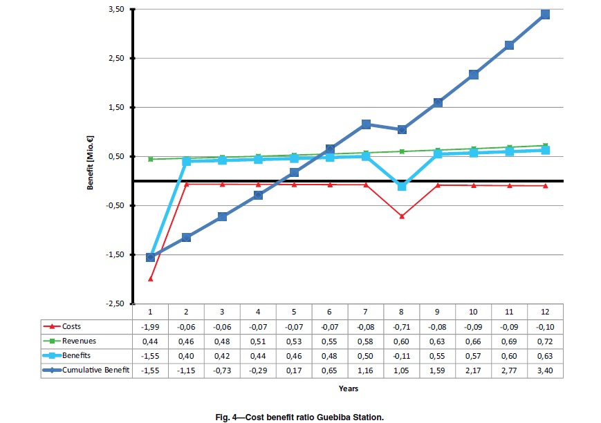
The maintenance and operation costs were calculated with 0.010 €/ kWh. For operational and maintenance costs as well as for electricity prices, an annual increase of 5% was determined on the experience of the last few years. After 7 years, a major overhaul is necessary. In coordination with gas-engine vendors, it was determined that costs for a new gas engine should be included. For this reason, the benefit line bends down in Year 7 (see Fig. 4, which shows the cost/benefit ratio on the basis of the parameters collected in Table 7).
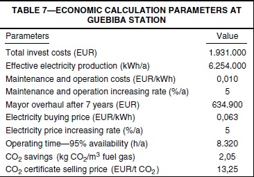
The economic analysis shows that from the second year, a continuous cash flow can be calculated. Taking all previously mentioned values into account, a payback period of less than 5 years was calculated.
Even with the necessary major overhaul, the cumulative cost benefit ratio stays in a positive balance.
the plant availability is 95%, the energy output of approximately 6,300 MWh/a at the Guebiba gas-use plant could cover a large fraction of the total Guebiba Station energy demand of 8,880 MWh/a. Thereby, the energy supply costs at this station could be reduced to approximately 30%.
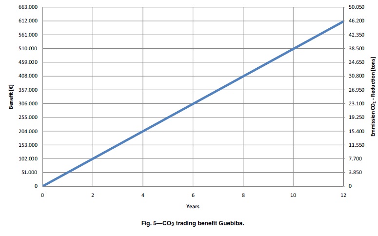
The influence of the CDM certificate has to be highlighted. At the TPS plants, there will not be a reduction in CO2 because the gas will just be burned in a gas engine instead of by useless burning in a flare.
But overall (consumer plus supplier), there is a reduction in CO2 pollution. Because of the self-production of electrical energy with the gas engine, it is not necessary to purchase as much electricity from a supplier who will thus emit less CO2. The CDM Program of the United Nations now offers the company that enacts these reductions certificates per ton of CO2 reduction. At a selling price of 13.25 € [average price for CER in Austria in 2009 according to Energy Exchange Austria (2009)] per certificate (1 certificate=1 ton CO2), an annual additional benefit of approximately 51.000 € is anticipated from the sale of the certificates.
To point out the positive economic effect of the CO2 certificate sale, Fig. 5 explicitly shows the economic benefit of the certificate trading. As mentioned, the power output at Tank Battery is approximately 30% higher than the output of Guebiba Station as a result of the higher amount of associated gas. At the same time, the energy demand of Tank Battery at 2,671 MWh/a is significantly lower than at Guebiba Station. For this reason, a significant surplus of electrical energy can be produced at the Tank Battery. By law, the local electricity supplier is obligated to buy this.
Conclusions
After extensive studies, technically and economically feasible powergeneration concepts for the use of associated gas to produce electric power were established. The unusable incoming associated gas composition with a very high CO2 and H2S content at the onshore facilities was a process and economic issue. An additional challenge was to find a common solution for both facilities, which was required by the operator (TPS) with special regard to operation, personnel training, and maintenance and capital expenditure. Conditioning by means of a membrane technology and electrical power generation by means of a gas engine can be applied at both onshore sites.
The concept presented enables a nearly self-sustaining operation of its two main oil-processing facilities, and beyond this the production of a significant surplus of electric energy at Tank Battery that can be sold to the local electricity supplier. A large portion of the associated gas, which was neglected as a potential power source in the past, can now be applied in the gas-use process.
By using the self-produced electricity and selling the surplus to the local electricity supplier, a payback time of less than 5 years was calculated for the installation of both onshore plants.
In addition to this economic aspect, the positive influence of the project to the environment because of a reduction in CO2 emissions should also highlighted. The technical concept set a milestone. The next step is the actual implementation of the project to approach TPS’s ambitious target—from liability to value.
References
Energy Exchange Austria (EXAA). 2009. Annual Report 2009
United Nations. 2010. Framework Convention on Climate Change: Clean Development Mechanism (CDM)
Matthias Bauer is project manager of multiple projects in oil and gas industry in Austria, Tunisia, Yemen, and Pakistan with TECON Engineering, where he’s been employed since February 2007. Within the paper related project, he was the project manager of TPS’ engineering partner TECON. He holds an MSc degree in mechanical engineering from the University of Cooperative Education.
Mario Köck works for OMV Yemen as the operations and maintenance manager. He is responsible for all onshore oil production activities within OMV Yemen’s Block S2, located in the desert of Yemen. He joined OMV as a production engineer in 2002 and was assigned to OMV Tunisia as development manager in 2007 where he was responsible for operations and projects in OMV Tunisia’s joint venture “Thyna Petroleum Services.”He holds a ME degree in petroleum engineering from the Mining University of Leoben.
Klaus Jörg is head of process engineering where he is responsible for all process related activities at the 3 TECON offices in Austria and Romania. Within the paper related project, he was the process lead engineer. He holds a MSc degree in process engineering and a PhD degree in mechanical engineering from the Technical University Vienna, Austria, and a MBA degree from the University of Klagenfurt.
Chandrasekhar Ramakrishnan joined TECON Engineering GmbH in After heading the process engineering department for the first 4 years, he lead the business development department for the next 4 years and was recently promoted to director of refining and upstream. He was involved in the flare gas recovery projects as a senior engineer,
closely cooperating with the project team in developing the suggested engineering solutions. He holds an MSc and PhD degree in chemical engineering from the Technical University of Vienna.


